


One of the most effective ways to measure airflow is through a method known as a traverse. While a traverse offers an accurate means of determining airflow, HVAC professionals rarely use it due to its intimidating nature. Let’s look at this time-proven measurement technique and see if we can remove some of the mystery surrounding it.
Traverse Background
Traverses have been used by air balancers for decades. For many, it is the gold standard of airflow measurement in commercial and residential systems.
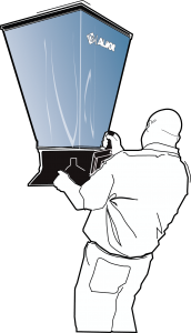
A traverse is a series of measurements used to determine the average velocity, or speed of air, moving through an opening. Air velocity is measured in a grid pattern through a variety of openings. They typically include: ducts, registers, grilles, filters, economizers, and grease filters. For purposes of this article, we will stick with the duct traverse.
Average air velocity, by itself, doesn’t provide a lot of information about ducts or the mechanical system. But once you combine it with a simple formula, you can determine airflow. The formula is: Area x Velocity = CFM. This formula can be broken down into the following components.
Area = the inside dimensions of the duct measured, in square feet.
Velocity = the average speed of air, measured in feet per minute (FPM) through the duct.
CFM = the calculated airflow, moving through the duct. Also known as cubic feet per minute.
Once average velocity readings are gathered and multiplied by the inside area of the duct, airflow is calculated. In the old days, these calculations were done manually. Thanks to the advances in test instruments today, they perform the math as you measure.
Field Applications
The number of places a traverse can be applied are plentiful. You can measure airflow on both the supply and return sides of the system. The easiest duct material to perform a traverse on is sheet metal. Common duct configurations to traverse are rectangular, round, and oval duct. Each has its own method for a proper traverse that we’ll discuss later.
 Flexible and fiberglass duct can present challenges if you attempt to traverse them. Two typical obstacles are finding an adequate location for the traverse and sealing the needed test port sites. I won’t say you can’t do it, but be aware, there are complications.
One of the most common applications for a traverse is to determine fan airflow. Depending on the installation, this is performed as a measurement of a return drop, or supply duct. Individual branch ducts can be measured using the same procedure. While this can be time consuming, it will help you evaluate what’s happening in problem rooms or areas.
You can compare measured traverse airflow to required airflow. Let’s say you have an 8” metal duct that feeds a bedroom and it is intended to deliver 200 cfm of air to the space. You can traverse the duct to see what’s really happening. If traverse airflow is only 100 cfm, you know you’ve got a problem.
Another application is on systems equipped with outside air. They often present challenges in determining how much airflow is being added to the return side of a system. A proper traverse of the outside air duct will leave no doubt to the amount of air coming in.
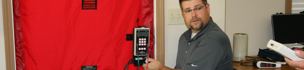
Test Instruments and Accessories
If you don’t have the appropriate instruments, you can’t measure. The good news is you can begin traversing with a minimum investment. The cost for test instruments to perform this level of measurement has dropped dramatically over the years. To traverse, you’ll need the following:
- Thermal anemometer
- Cordless drill with 3/8” bit
- 3/8” test port plugs
- Duct Jigs – to speed up test port installation
 Do your research before purchasing any test instruments. You get what you pay for. Each instrument has its own learning curve, so practice and learn how to operate it before measuring. Something as simple as improper probe position can throw your readings off.
As your skills increase, explore other test instrument options such as a manometer and pitot tube or velocity grid to perform traverse measurements at other locations.
Fundamental Guidelines
There are some fundamental guidelines you need to follow when performing a traverse. If you ignore them, you’ll get some really goofy measurements.
The first fundamental is to find an acceptable test location in the duct. This usually presents the biggest challenge since a “by-the-book” traverse requires a long, straight run, with no turns, takeoffs, or transitions in it. The ideal length is 10 duct diameters. To give you an idea how long this is, if you have a 12” round duct, it would need a straight length of 10 feet, or 120 inches (12 x 10 = 120) to be traversed “by the book.”
It can be hard, if not impossible, to find ducts that meet these requirements, so many just say it can be done. With a little practice, successful readings can be obtained on duct lengths as low as 5 duct diameters. If you’re in a pinch, try measuring on shorter length ducts, it’s better than guessing.
Next, you’ll need to install test ports for measurement. Their location is 80 percent downstream the length of duct. This is so the air has the chance to straighten out and reduce turbulence before measurement. Going back to the example of the 12” round duct that is 10 feet long. Test ports would be located 8 feet, or 96 inches downstream (120” x 80% = 96”).
A rectangular duct needs test ports installed in the short side of the duct. A round duct needs two test ports installed 90-degrees apart from each other.
There are two frequently-used traverse methods that determine the installation of your test ports and measurements. The first is called the “equal area” method. Ports are installed approximately 2 to 3 inches apart and measurements are taken in an equal grid pattern inside the duct. The second style is called the “Tchybecheff” method. It uses a lot of math to calculate test port and traverse sites. It is mainly used when specified by an engineer and requires dedication to master.
Once your test locations are set, you’ll obtain between 16 to 64 velocity readings inside the duct. A good rule to remember is the more readings you take, the greater your chances are for an accurate traverse. Once the velocity readings are obtained, they are averaged and plugged into the CFM formula along with the inside duct area.
Perform a Traverse
 To sum up the steps we’ve covered so far, you can break a traverse down into six steps. Some of these steps aren’t needed if your test instrument performs the associated functions. Be sure to read manufacturer’s instructions first.
Step One: Find an acceptable test site in the duct you want to traverse.
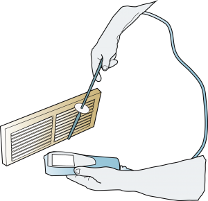
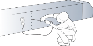
Step Two: Determine test port location and install them with a drill.
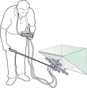
Step Three: Use a thermal anemometer to measure multiple velocity readings in a grid pattern.
Step Four: Add up all your velocity readings and divide by the number of readings taken. This is your average velocity.
Step Five: Determine inside duct area in square feet. Multiply width times length and divide by 144 to arrive at this measurement.
Step Six: Plug the average velocity and duct area (in sq. ft.) into the CFM formula. Voila! You have an airflow reading.
The hardest part is getting started. Make the decision to become a student of traverse measurements and take the first step.
There’s so much more that can be said on this subject — I am barely scratching the surface, I’m providing a broad overview to take make it a bit more digestible.
All illustrations © 2017, National Comfort Institute, Inc.
Leave a Reply
You must be logged in to post a comment.